Installer’s Guide
CH PUMP CONTROLLER
The controller is easy to operate. It performs the function of CH pump activation if the temperature of water in the boiler reaches the set value. The controller switches the pump off if the temperature drops below the set threshold (minus hysteresis in ST-21). The ST-19 and ST-21 controllers are equipped with the anti-stop function preventing the pump’s blocking by the deposited scale. The pump is switched on for several minutes every 10 days beyond the heating season. It is possible to switch on the pump in the manual mode in all controllers. Detailed information on this topic may be found in the user’s manual of particular devices.
CONTROLLERS COOPERATING WITH THE BLOW-IN FAN
The fan operates until the boiler reaches the set temperature. Then, it proceeds to its support mode. After a period of several minutes (more than ten minutes), blowthroughs are switched on that support the combustion process as well as prevent the generation of gases in the damped boiler. This occurs in repeating intervals. The blowthrough time is ever several (more than ten) seconds. Too short breaks in the blowthrough may result in water boiling in the boiler. The drop of temperature below the set temperature minus hysteresis results in the repeated activation of the blow-in. The regulators also control the operation of the CH pump and the DHW pump (not all types). Adjusting the blow-in force is essential for proper combustion. Too small blow-in equals poor combustion, and the boiler fails to achieve power suitable to heat the water in the installation. Too high blow-in force equals fast combustion and loss of energy escaping to the atmosphere through the chimney. It is good to use a zPID controller with a smoothly and automatically regulated blow-in power depending on the set temperature and the flue gas temperature on the boiler.
CONTROLLERS FOR BOILERS WITH FEEDERS
The operation of pumps and the fan is the same as in controllers without feeders. Additional parameters which require adjustment are the feeder’s operation and pause in the operation and support mode. The correct adjustment of operation parameters is a necessary condition for good and effective combustion, and support maintains the boiler in the combustion status. The controller has a temperature protection for the feeder. If the temperature increases above the alarm threshold, the alarm switches on, the controller activates the feeder for several to more than ten minutes. The fuel from the feeder is moved to the boiler. If the increase in temperature results from the flame’s backing up to the feeding screw, this function prevents the fuel in the feeder from ignition. The time of operation and pause of the feeder as well as of the fan in support is a very important parameter. If the operation time in support is too long and (or) the pause time in support is too short, the temperature in the boiler may increase quickly. The protections will be activated then (switching off the blow-in and the feeder). However, water in the CH installation may boil if there is no sufficient heat collection.
VALVES COOPERATING WITH OUR CONTROLLERS
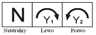
A whole range of valves with actuators with three-point control 220V cooperates with our controllers. The rotational speed can reach up to 1,500s/90°. Description of rating plate:

| Neutralny | Neutral |
| Lewo | Left |
| Prawo | Right |
N – Power supply voltage 230V AC Y1 – Control signal: open 230V Y2 – Control signal: close 230V
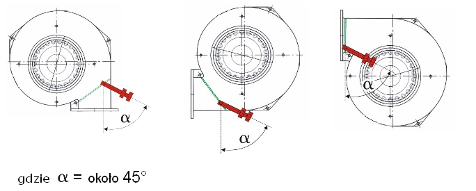
Method of Adjusting the Fan’s Flap in the Charging Boiler zPID
The method of adjusting the fan’s flap before the heating season is a very important element of the boiler’s correct operation, in particular during zPID control. In the first place, the user should preset the flap’s location (as well as the load screw) depending on the fan’s model and settings:

| Gdzie α = około 45o | Where α=approx. 45o |
The user may precisely verify the correct adjustment of the flap on the fan mounted on the boiler when the boiler is fired up (in order to adjust the relevant location for an appropriate chimney draught). In order to do this, the user should select the function “manual operation” in the controller and verify the flap’s operation for various fan powers.
When the blow-in operates, the correctly adjusted flap should begin to tilt no sooner than at approx. 10÷20% of the blow-in’s power. Operation on lower rotations is correct with minimum draught, through gaps in the structure of the fan itself and of the boiler.
